TH001 Manual
Posted by SEBASTIAN ZOTA

This manual covers the following models*:
T822K,L • T827K
* Images are for reference only and may not represent the actual thermostat.
Pre-installation checklist
Check package contents:
- Thermostat
- Wall anchors & screws (2 each)
Before you begin, make sure you have:
- No. 2 Phillips & small pocket screwdrivers
- Hammer
- Level (optional)
- Pencil
- Drill and bit (3/16” for drywall, 7/32” for plaster)
Must be installed by a trained, experienced technician
Read these instructions carefully. Failure to follow these instructions
can damage the product or cause a hazardous condition.

CAUTION: ELECTRICAL HAZARD
Can cause electrical shock or equipment damage. Disconnect power before beginning installation.

MERCURY NOTICE
If this product is replacing a control that contains mercury in a sealed tube, do not place the old control in the trash. Contact your local waste management authority for instructions regarding recycling and proper disposal.
Product application
This thermostat provides control of:
- 24 Vac heating systems (T822)
- 750 mV or 12 Vdc heating systems (T827K)
- 24 Vac cooling systems (T822L)
System Types
- Gas or oil
- Warm air, hot water, high-efficiency furnaces, heat pumps, steam, gravity
- Normally closed hot water valves (T822K)
- 2-wire cooling systems (T822L)
- Normally open hot water valves (T822L)
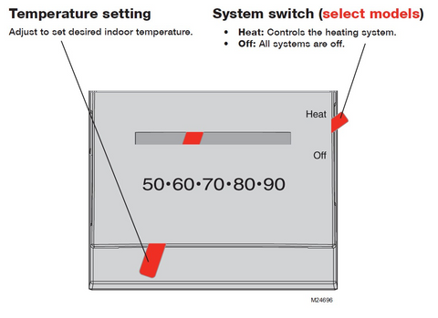
System Settings
- Heat, Off (select models only)
Specifications
Temperature Control Range
- 50° to 90°F (10° to 32°C)
Operating Ambient Temperature
- 0° to 120°F (-18° to 49°C)
Operating Relative Humidity
- 5% to 90% (non-condensing)
Dimensions (vertical model)
- 2.88W x 4.75H x 1.5D (inches)
- 73W x 121H x 38D (mm)
Dimensions (horizontal model)
- 4.75W x 2.88H x 1.5D (inches)
- 121W x73H x 38D (mm)
Electrical Ratings
| Terminal | Voltage (50/60Hz) | Running Current | |
|---|---|---|---|
| W1 | Heating | 20-30 Vac | 0.02-1.2 A |
| (Powerpile) | 750 mVdc | 100 mAdc | |
| (DC Powered) | 12 Vdc | .55 A | |
| Y2 | Cooling | 20-30 Vac | 0.02-1.2 A |
| (Normally open hot water valve.) | 20-30 Vac | 0.02-1.2 A | |
| 1 | T822K and T827K | ||
| 2 | T822L | ||
Base installation
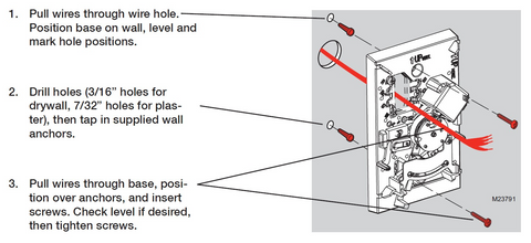
Wiring
- Loosen screw terminals, insert bare wires beneath screws, then re-tighten screws.
- Push any excess wire back into the wall opening
- Plug the wall opening with nonflammable insulation to prevent drafts from affecting thermostat operation.
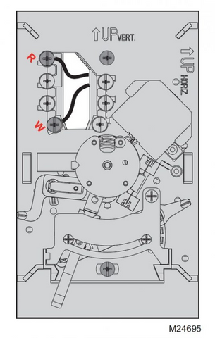
Terminal Designations
Wire specifications
Use 18-gauge thermostat wire. Shielded cable is not required.
| R | Heating power. Connect to secondary side of heating system transformer. |
| W1 | Heat relay. |
| Y2 | Cool relay, or normally open hot water valve. |
| 1 | T822K and T827K |
| 2 | T822L |
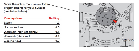
Set heat anticipator (model T822K only)
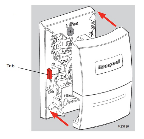
Thermostat mounting
Operation