

How to Install a TH001 Heating/Cooling Thermostat in Your System
Posted by SEBASTIAN ZOTA

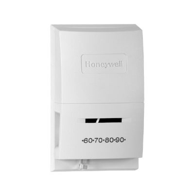
T822, TS822 Heating/Cooling Thermostats
Features
- T822A, D, F and TS822A control heating systems.
- T822C, E control cooling systems.
- T822G controls heating or cooling systems.
- T822F provides Auto-On System switching.
- T822D, F, G heating anticipators are adjustable.
- T822A and TS822A heating anticipators are not
adjustable. - T822C, F, G cooling anticipators are not adjustable.
- Coiled bimetal operates quiet, dust-free mercury
switch. - All wiring connections are made on back of
thermostat. - All models are mounted directly on wall or on standard
vertical outlet box. - T822A, C, D and TS822A are available with positive Off.
- All models have vented covers for better air flow and
improved temperature sensing.
Application
T822 models provide low voltage (millivoltage) control of heating or cooling systems.
Specifications
The specifications given in this publication do not include normal manufacturing tolerances. Therefore, this unit may not exactly match the listed specifications. Also, this product is tested and calibrated under closely controlled conditions, and some minor differences in performance can be expected if those conditions are changed.
Tradeline Models
Tradeline models are selected and packaged for ease of handling, ease of stocking, and maximum replacement value. Tradelinespecifications are the same as those of standard models except as follows:
Tradeline Models Available:
T822D Heating Thermostat used for low voltage heating applications with adjustable heat anticipator.
TS822A Heating Thermostat used for 250/500 and 750 mV applications with nonadjustable heat anticipator.
Additional Features:
- T822D and TS822A available with positive Off.
- T822D models available with heat anticipator factory set at
0.2A for electric heat applications. - Temperature range stops available on some Tradeline
models.
Standard Models
Standard Models Available:
T822A Heating Thermostat used in low voltage heating applications. Nonadjustable heating anticipator.
T822C Cooling Thermostat used in low voltage cooling applications. Nonadjustable cooling anticipator.
T822D Heating Thermostat used in low voltage heating applications. Adjustable heat anticipator.
T822F Heating Thermostat used in low voltage heating applications. Adjustable heat anticipator and On-Auto Fan
switching.
T822G Heating or Cooling Thermostat used in low voltage heating or cooling applications. Works with series 20 heating applications. Adjustable heat anticipator. Nonadjustable cooling anticipator.
TS822A Heating Thermostat used in millivoltage heating applications.
Electrical Ratings:
T822A: 0 to 1.2A at 30 Vac; 1.5A at 24 Vdc.
T822C: 1.0A running, 5.0A inrush at 25 Vac.
T822D,F,G: 0.18 to 0.8A at 30 Vac/Vdc.
TS822A: 0.1A at 250/500 and 750 mV.
Anticipator Ratings:
T822A: Nonadjustable. Factory set from 0 to 0.4A.
T822C: Nonadjustable. Factory set from 0 to 1.0A.
T822D: Adjustable from 0.18 to 1.0A or 0.3 to 1.2A.
T822F: Adjustable from 0.18 to 1.0A.
T822G:
Heating Anticipator: Adjustable from 0.18 to 1.0A.
Cooling Anticipator: Nonadjustable. Factory set from 0 to 1.0A.
Switching:
Heating Thermostats: Spst mercury switch makes R to W on temperature fall.
Cooling Thermostats: Spst mercury switch makes R to Y on temperature rise.
Temperature Setting Range (Specify When Ordering):
Standard Heating Models: 55° F to 95°F (13°C to 35 °C).
Positive Off Heating Models: 60° F to 95°F (16°C to 35°C).
Standard Cooling Models: 55° F to 95°F (13 °C to 35°C).
Positive Off Cooling Models: 55° F to 85°F.13°C to 29°C).
Dimensions: See Fig. 1.
Mounting Means: Two screws through thermostat mounting holes to wall or vertical or horizontal mounting box.
Optional Specifications:
Positive Off Switch: Temperature setpoint lever provides complete control circuit shutdown. Does not replace power supply disconnect switch.
Adjustable Range Stops: Limits setpoint temperature range.
Accessories:
104944A Calibration Wrench.
193121A Mounting Plate to mount thermostat on horizontal or vertical outlet box.
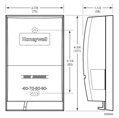
Fig. 1. T822/TS822 dimensions in in. (mm).
Installation
When Installing this Product...
- Read these instructions carefully. Failure to follow them could damage the product or cause a hazardous condition.
- Check the ratings given in the instructions and on the product to make sure the product is suitable for your application.
- Installer must be a trained, experienced service technician.
- After installation is complete, check out product operation as provided in these instructions.

Caution
Electrical Hazard.
Can cause personal electrical shock or equipment damage.
Disconnect power supply before beginning installation.
Location
Locate the thermostat about 5 ft (1.5m) above the floor in an area with good air circulation at average temperature. Do not mount the thermostat where it can be affected by:
— drafts or dead spots behind doors or in corners.
— hot or cold air from ducts.
— radiant heat from the sun, fireplaces, or appliances.
— concealed pipes and chimneys.
— unheated (uncooled) areas behind the thermostat, such as an outside wall.
Mounting and Wiring
- Disconnect power supply before beginning installation.
IMPORTANT
All wiring must comply with local codes and ordinances.
NOTES:
— The T822 or TS822 Thermostats are designed to be wall or vertical outlet box mounted.
— In a 250 or 500 mV applications, use No. 14 wire, if possible and make the run as short as possible (consider this when selecting a location).
— For a 750 mV application, the maximum wire lengths are shown in Table 1.
Table 1. Wire Length.
| Wire Size | Maximum Length 2-Wire Cable | Maximum Combined Length 2-Single Wires | ||
|---|---|---|---|---|
| (ft) | (m) | (ft) | (m) | |
| No. 18 | 30 | 9.0 | 60 | 18.0 |
| No. 16 | 50 | 15.0 | 100 | 30.0 |
| No. 14 | 80 | 24.5 | 160 | 49.0 |
- In replacement applications, check existing thermostat wires for cracked or frayed insulation. Replace any wires in poor condition.
NOTE: If wire is plastered into the wall, make a hole next to the wires and loosen them so they can be pushed back into the wall later
- In new installations, run wiring, if necessary, to the thermostat location.
- Connect the wires to the terminals on back of thermostat. See Fig. 2-8 for internal schematics and typical hookup diagrams.
- Remove thermostat cover by pulling outward from indention on the right or left side of cover until it snaps free of thermostat base. Carefully remove and discard foam plastic shipping insert protecting switch and bimetal assembly during shipping.
- Set the adjustable heat anticipator indicator (select models) to match the current draw of the primary heating control (see Heat Anticipator Setting).
- Push excess wire back through the hole and plug any opening with insulation to prevent drafts that can affect thermostat performance.
- Loosely fasten the thermostat to the wall or outlet box with a screw through the top mounting hole. Do not tighten.
- Level the thermostat exactly using a level device. Tighten the mounting screws.
IMPORTANT
This thermostat is calibrated at the factory, mounted at true level. Any inaccuracy in leveling during the mounting causes control point deviation.
- Replace thermostat cover.
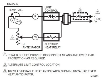
Fig. 2. T822A,D in typical electric heat application.
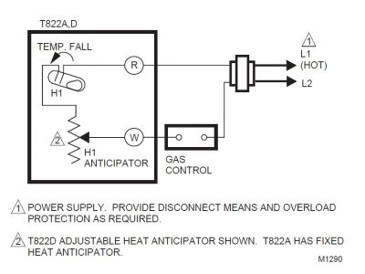
Fig. 3. T822A,D in typical gas heating application.
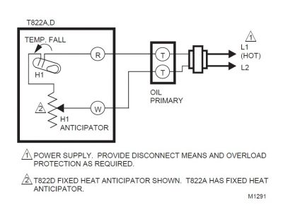
Fig. 4. T822A,D in typical oil heating application.
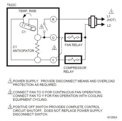
Fig. 5. T822C in typical cooling application.
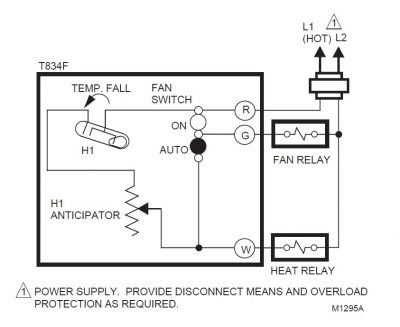
Fig. 6. T822F in typical heating application.
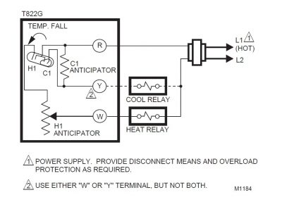
Fig. 7. TS822G in typical heating or cooling application.
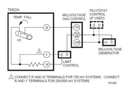
Fig. 8. TS822A in typical heating application.
Settings & Adjustments
Temperature Setting (All Models)
Move the temperature setting lever to the desired control point on the temperature scale.
NOTE: On positive Off models, the control circuit is broken when the lever is moved to the extreme low end of the temperature scale.
T822F System Switching
The Fan switch control system operation as follows:
- Auto: For gas or oil heating systems, the fan operates in response to the thermostat call for cooling.
- On: The fan operates continuously.
Heat Anticipator Setting (T822D,F,G Only)
IMPORTANT
- — The T822D,F,G has an adjustable heat anticipator and operates correctly only if the anticipator is adjusted to match the current draw of the primary control.
- — Use the T822D,F,G only on systems with current draws that fall within the range of the heat anticipator. Do not use this device on Powerpile (millivolt) systems.
- A current rating is usually stamped in the nameplate of the primary control. Set the adjustable heat anticipator indicator to match the value given on the nameplate.
- If the current rating is not available, proceed as follows to determine the rating:
- Turn off the power.
- Wire thermostat, except connection to W terminal, but do not mount it on the wall.
- Connect ammeter between W wire and W terminal on thermostat in series with primary control.
- Prepare system for operation.
- Turn on power.
- Turn System switch to Heat.
- Increase thermostat setpoint, as necessary, to start system operating.
- With system operating through ammeter, wait one minute, then read ammeter.
- Turn System switch to Off and turn off power.
- Adjust heat anticipator to match reading on ammeter.
- Disconnect ammeter, reconnect W wire, and mount thermostat. Continue with system checkout.
NOTE: The heat anticipator may require further adjustment for best performance. To lengthen burner-on time, move indicator in direction of longer arrows but not more than a half-scale marking at a time. To shorten burner-on time, move indicator in opposite direction.
Checkout

CAUTION
Checkout Method Hazard.
Can damage thermostat heat anticipator.
Avoid checking thermostat operation by shorting across system control terminals.
T822A,D,F and TS822A Heating and T822G Heating or Cooling Thermostats
IMPORTANT
- — T822A,D,F and TS822A can only be installed in heating applications. Perform only steps 1-5.
- — T822G can be installed in either heating or cooling applications. If installed for heating, perform steps 1-5. If installed for cooling, perform step 6.
- Set T822F Fan switch at Auto. Fan operation is controlled by the thermostat.
- Move temperature setting lever about 10°F (6°C) above room temperature.
- Gas or oil heating systems: Heating starts immediately. Fan starts after short delay.
- Electric heating systems: Heating and fan start immediately.
- Move temperature setting lever about 10°F (6°C) below room temperature.
- Gas or oil heating systems: Heating stops immediately. Fan stops after a short delay.
- Electric heating systems: Heating and fan stop immediately.
- Set T822F Fan switch to On. Fan runs continuously.
- Set temperature lever and T822F Fan switch to desired settings.
CAUTION
Equipment Damage Hazard.
Can short-cycle air conditioner compressor.
Install five-minute time delay to prevent operating compressor for five minutes after thermostat turns off compressor or for five minutes after system receives power.
Avoid operating T822G Thermostat in cooling applications when outdoor temperature is below 50°F (6°C).
See air conditioner manufacturer recommendations.
- For T822G cooling applications only:
- To prevent compressor short cycling, install a fiveminute time delay. (The time delay will not activate the compressor for five minutes after the thermostat turns off the compressor or for five minutes after the system receives power.)
- Move the temperature setting lever about 10°F (6°C) below room temperature. Cooling and fan should start immediately. Move temperature setting lever about 10°F (6°C) above room temperature. Cooling and fan should stop immediately.
T822C Cooling Thermostats
CAUTION
Equipment Damage Hazard.
Can short-cycle air conditioner compressor.
Install five-minute time delay to prevent operating compressor for five minutes after thermostat turns off compressor or for five minutes after system receives power.
Avoid operating T822C Thermostat in cooling applications when outdoor temperature is below 50°F (6°C). See air conditioner manufacturer recommendations.
- To prevent compressor short cycling, install a fiveminute time delay. (The time delay will not activate the compressor for five minutes after the thermostat turns off the compressor or for five minutes after the system receives power.)
- Move temperature setting lever about 10°F (6°C) below room temperature. Cooling and fan start immediately.
- Move temperature setting lever about 10°F (6°C) above room temperature. Cooling and fan stop immediately.
CAUTION
Checkout Method Hazard.
Can damage thermostat heat anticipator.
Avoid checking thermostat operation by shorting across system control terminals.
Recalibration
These thermostats are calibrated at the factory and should not require recalibration. If the thermostat seems out of adjustment, first check for accurate levelling. To check calibration:
- Move the temperature setting lever to the low end of the temperature scale.
- Remove the thermostat cover. Move the temperature setting lever until the switch just makes contact. (The mercury in the switch will drop to the contact end of the
tube.) - Replace the thermostat cover and wait five minutes for the cover and the thermostat to lose the heat it has gained from your hands. (If the thermometer pointer and the temperature lever indicator read approximately the same, no recalibration is needed.)
- If recalibration appears necessary, use this procedure:
- Place the temperature setting lever at the same setting as the thermometer.
- Remove the thermostat cover.
- Insert 104994A Calibration Wrench (ordered separately) onto the hex nut under the coil. See Fig. 10. Holding the setting lever so it does not move, turn the wrench clockwise until the switch just breaks contact.
- Remove the wrench and replace the thermostat cover.
- Move the temperature setting lever to a low setting. Wait at least five minutes for the temperature to stabilize.
- Slowly move the temperature setting lever until it reads the same as the thermometer.
- Remove the cover. Holding the temperature setting lever so it does not move, reinsert the wrench and carefully turn the wrench counterclockwise until the mercury just rolls to the left end of the tube, but no farther.
- Recheck the calibration by setting the thermostat System switch for the desired operation.
- Replace the cover.

Fig. 9. Recalibrating thermostat.
